Braking choppers – overview
How does a braking chopper work?
A braking chopper or chopper is connected to a DC link. When a set brake voltage threshold is reached it switches an internal or external resistor (depending on the series) in a clocked mode.
Thus the chopper effectively limits the voltage in e.g. a DC link.
Typically, a braking chopper is used with a frequency inverter for demanding braking tasks (up to continuous braking) or to protect regenerative frequency inverters in the event of a mains failure.

Applications
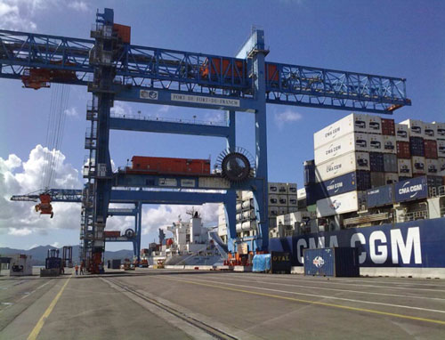
Braking choppers are used for drives with a large moment of inertia or the need for fast braking. As a rule, they are used for drives in materials handling, travel and lifting applications, and test stands.
The following articles show some applications of KIMO® Braking choppers:

Braking choppers for external braking resistors
11 – 22 kW
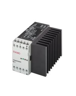
TRANSOMIK® BC1
Features
- Operation with frequency inverters for supply voltages up to 3AC 460 V
- Brake voltage threshold 670 / 770 V
Applications
- Drives with large inertia
- Drives with requirement for rapid braking
- Drives for transport, long travel and hoisting applications
- Retrofit to existing inverters without braking chopper

Braking choppers for external braking resistors
40 – 1200 kW
TRANSOMIK® BC2
Features
- Operation with frequency inverters for supply voltages up to 3AC 460 V,
- 575 V, 690 V
- Brake voltage threshold 670/770 V,
- 840/960 V, 1065/1155 V
- Increased power with optional fan
- Can be paralleled for higher powers
Applications
- Drives with large inertia
- Drives with requirement for rapid braking
- Drives for transport, long travel and hoisting applications
- Retrofit to existing inverters without braking chopper

 All KIMO® Braking chopper in an overview